-
Amazon Deals - ToS - Warp
You are using an out of date browser. It may not display this or other websites correctly.
You should upgrade or use an alternative browser.
You should upgrade or use an alternative browser.
broadband ut300 modem,link light stays on forever and had to restart to get connected
- Thread starter MEGAN
- Start date
- Replies 35
- Views 4,282
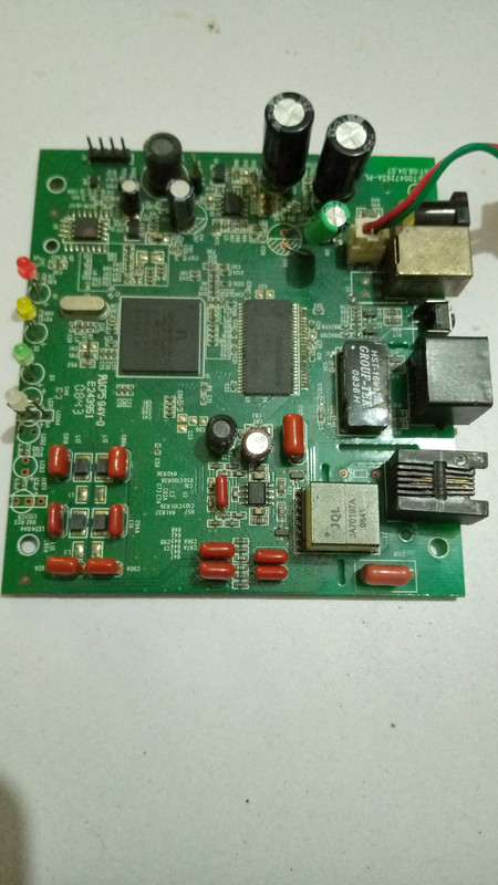

It seems they've used the same model number - ut300r2u - for different board versions. Mine looks like above. The flash chip on mine is a 48-pin one, while yours seems to be a SOP8. IC versions too appear to be different. And the board I have, uses a 10v 550ma adapter.
So the next thing I'd suggest would be to google the broadcom chip number (not clear in your photo), find its datasheet, find out which pins are power inputs and check those. For example, the rectangular chip in the middle is RAM chip. In my case it is K4S641632K-UC75, a 64Mb SDRAM chip. As the datasheet shows, the Vdd pin is the first pin (counting from the indent in the corner) and the GND pin is the one directly opposite on the other row. For this model, the naming shows that it is LVTTL and that Vdd should be 3.3v. And for the 48-pin 16Mb flash chip my board has, pin 37 is the Vcc and it needs to be around 3v (2.7-3.6v range). RAM and broadcom processor votages are the important ones, so check those first.
The four pins labeled J5 in your photo (in the top corner, near the red led) appear to be serial port. Check their voltages to confirm TTL or RS232 and then you can try reading them using arduino or some sort of serial to usb converter.
Last edited:
If yours uses a 5v 1A adapter, it should be easy to rule out any power issues by testing with some suitably powerful phone charger. Connect power pins of the charger (pins 1 and 4 in usb-a) to appropriate points on the board. Check how barrel port is soldered to find out where to connect, if positive and negative terminals are not labeled on the board. Usually in case of the barrel plugs, outside is negative and inside pin is positive.
wow thats some very extensive thing for me to do sir ,i am very novice at electronics ,i just thought may be some parts would be available to resolder into the board. but yes i will try that data sheet thing soon , that broadband chip gets very hot though.thank you for supporting the insight of this board. sir if the lan transformer is gone bad ,anything can be done ? in a vid i saw the lan light was non stop lit up alternative pattern 101010 like in seconds . then he stripped the lan transformer ,then other ports worked for him. but we have just one lan port in our board. but also the dsl line is lit with no phone wire connected or not . i will try that broadband datasheet as you advised first.
i checked the voltages of WINBOND/W9864G6GH-6 they are all good ,those vdd ,vddq according to chip data. but i dont see how i can check volatages for this BCM6332KFBG broadcom chip,i also checked the j5 pins , ground pin is at top and others are 3..3 volts. i have a epprom ch341a.. would this be any use in this matter ? i dono much about arduino
Last edited:
after learning few from vids and reading , the previous day to the modem got irreversible symptoms was a lightening thunder rain night. my assumptions is it messed up the ethernet port or isolation transformer or adsl phone line chips may be. any one can give me few ideas about to protect modem , really it was just modem this time, it wasnt my computer ,but in future i dont want to take risks. gota protect these lines travelling to my mobo and destroying everything in its way. or i should simply take off adsl phone line off when i am not using it. and computers ethernet lan too.??
APC's computer UPSes used to come with a phone-line and RJ45 ports which were supposed to offer surge protection. Not sure if their new ones have it or not. Googling for "phone line surge protection" or "RJ45 surge protection" shows some devices available from US but I don't think they are available locally.
I've seen 2 instances of blown ports - both with the local broadband providers and both possibly due to the providers' lines shorting with power cables from falling branches or something like that. In both, only the specific lan port, into which the incoming line was connected, was blown. Other ports were working correctly with no damage to devices connected through them.
I've seen 2 instances of blown ports - both with the local broadband providers and both possibly due to the providers' lines shorting with power cables from falling branches or something like that. In both, only the specific lan port, into which the incoming line was connected, was blown. Other ports were working correctly with no damage to devices connected through them.
oh thats good to hear , just the port goes bad but leaving connected computer fine. thats a relief to hear. i was getting paranoid for my computer parts blown off. there are diy surge protectors for extension boxes but have not come across for rj11 phone lines. actually this comes under responsibility(major part) of isp provider to safe guard their lines well ,wish my modem had 2 lan ports hehe , but anyway the dsl line light always solid (no flickr) no matter what, today i even heat gunned the broadcom chips with flux for about 30-40 secs , ( source internet vid saying when all lights are on ,may be some chip got desoldered ) but it was the same result as before , putting the power - power ,dsl light ,keeps lit - no change with input of phone line , then lan light pc/usb will on off on off cycle when lan is put, in computer i can see its trying to connect modem ,and its forever. if i try with usb , the red light instead of green light (lan light) but it keeps lit as before when normal. remote usb ndis doesnt come as before . so usb line gone too i guess.
all these years for about a decade this is the first time i came across this problem lightening adsl and modem boom ! i am surprised shocked seeing so many of them had thier computers blown off , even with monitors ! this is scary. we dont even have black friday sales as they have lol to get cheaper electronics .
all these years for about a decade this is the first time i came across this problem lightening adsl and modem boom ! i am surprised shocked seeing so many of them had thier computers blown off , even with monitors ! this is scary. we dont even have black friday sales as they have lol to get cheaper electronics .
These are all variants of D-Link_DSL-2500U. With a usb-to-serial adapter (current cost around Rs 300) you can get boot logs out of the machine which I guess will be more helpful in figuring out the issue. For example, here's a Russian using the serial port on a similar board, to figure out the flash was corrupt.
by the way when i examined the board little much closer today, i think i found few capacitors blown off ! in front of isolation transformer c34 c35 c133 c19 , when i shorted 34 35 133, the board switches off ,but not when c19 . but i am unsure if the capacitors are left unjoint purposefully or it was blown due to some power problems. mm and i looked in the pics of your last post.it had the capacitors empty too in front of lan transformer. so just the usb cable is enough to see whats going on inside this modem ? wish it had little more lesser price tho. thanks for keepin on this discussion 🙂 i have ch341a eeprom ,could be this any use here ?
also this is the chip 25X16VSIG - i read the voltages ,vcc shows 3.7 v as per data sheet . i desoldered the chip and kept it in my ch341a usb flash programer. it detects the chip and even read the whole bios in the chip.. now i guess i have to try flash ut300 to it ,but i am in dilemma now. been searching for ut300 firmware bin file for a while now. not getting it anywhwere, but made a back up of my present flash bin from this chip.
also this is the chip 25X16VSIG - i read the voltages ,vcc shows 3.7 v as per data sheet . i desoldered the chip and kept it in my ch341a usb flash programer. it detects the chip and even read the whole bios in the chip.. now i guess i have to try flash ut300 to it ,but i am in dilemma now. been searching for ut300 firmware bin file for a while now. not getting it anywhwere, but made a back up of my present flash bin from this chip.
Last edited:
The image I have is the same one as in the post here. I don't know if that's the whole chip image, but I guess it is. I don't have a flash reader to pull one off of mine.
oh ok, i tried to read the board with ch41a programmer through serial port in putty, but it was all gibberish , i tried ,ubt i think it might be due to not doing through jumper cables too. may be i will buy it later and try it all again.. or will just throw away this board to scrap . from another forum one person said it might be due to cpu oscillator , may be i will try changing it too.
Oh I didn't know ch341a programmers could be used as serial readers. Assuming everything else went right, perhaps rx tx pins on the serial port were misidentified? You could switch and try.
yes it was all garbled grey boxes coming in putty ,got to know that its because of bad jumper cables, i have to buy it, i dont have any, i tried soldering the jumper wires, but its not joining ,i am afraid not to heat the usb too much . can you tell me if the oscillator is bad,how much hertz i should buy for the modem ? actually how to even check if its gone bad
Similar threads
- Replies
- 27
- Views
- 9,560
- Solved
- Replies
- 47
- Views
- 106,834
- Replies
- 1
- Views
- 7,861
- Replies
- 54
- Views
- 4,540